

TSD 40 Manual: Connecting and Setting the Low-Voltage Disconnect.
The TSD 40 deep-discharge protection protects 12 V and 24 V batteries in two stages: comfort loads on OUT 1 are switched off first, while important loads on OUT 2 stay on until the second threshold. A buzzer warns before every disconnection, and reconnection is automatic. Up to 40 A per output.
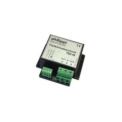
Application and intended use
The remote-controllable, two-stage TSD 40 battery deep-discharge protection protects batteries from damage caused by deep discharge. Conventional devices do this by switching off all loads at once. With the TSD 40, important and safety-related loads keep running, while comfort loads are switched off in a first step as the voltage drops. An audible alarm warns before every disconnection; once the voltage rises above the thresholds again, the TSD 40 reconnects automatically.
With the highest switching threshold (DIP 2/3 set to 1/1), simple energy management can be implemented alongside the deep-discharge protection: an additional cool box, a heating mat or a water heater is only activated when the alternator is running or the solar system supplies enough energy. With the optional control panel, the TSD 40 becomes a remote-switchable battery isolator.
Please note: loads that are not connected via an output of the TSD 40 can still discharge the battery.
The TSD 40 operates only on extra-low DC voltage of 12/24 V. It is designed for use on yachts and in vehicles and may only be operated in enclosed spaces protected from rain, moisture, dust and condensation. Do not install where there is a risk of explosion from gas or dust, and not outdoors.
Safety instructions, warranty, liability
- No modifications may be made to the unit, otherwise the CE mark becomes void.
- Connection may only be carried out by qualified electricians.
- Observe the correct polarity of the batteries and connections.
Scope of delivery: TSD 40 deep-discharge protection and manual. The manual is part of the delivery; keep it and pass it on to any subsequent owner.
Warranty: two years from the date of purchase. Material or manufacturing defects are remedied free of charge if the unit is sent to the manufacturer carriage paid, the proof of purchase is enclosed, the unit has been used as intended and no third-party spare parts have been fitted or interventions made. Excluded is damage caused by overvoltage at the inputs or reverse polarity, ingress of liquids or oxidation due to condensation, and lightning strike; consequential costs and natural wear are not covered. Please describe the defect in detail; shipments sent carriage forward cannot be accepted. philippi accepts no liability for damage resulting from incorrect installation or improper operation.
Connection

The TSD 40 is connected between the battery and the loads to be protected. Loads can be connected to OUT 1, OUT 2 or both; this does not affect the function.
- OUT 1: comfort or “luxury” loads that are switched off early.
- OUT 2: loads that should stay on until the battery is fully discharged.
- Important: without a remote control connected, terminals FA(1) and FA(2) must be bridged for the deep-discharge protection to be active (as delivered).
Fuse the supply cable from the battery to the TSD 40 as close to the battery as possible, according to the cross-section:
| Current load | Cable cross-section |
|---|---|
| up to 10 A | 1.5 mm² |
| up to 16 A | 2.5 mm² |
| up to 25 A | 4 mm² |
| up to 40 A | 6 mm² |
Settings with the DIP switches
The TSD 40 has a 4-way DIP switch. To set it, remove the housing cover after loosening the two housing screws, preferably before connecting the cables. Position 0 = down, 1 = up.
| DIP switch | Setting |
|---|---|
| DIP 1 | 0 = 12 V operation, 1 = 24 V operation |
OUT 1, comfort loads (DIP 2/3, delay 5 min; at the OUT 2 switching thresholds: 50 s):
| DIP 2 / DIP 3 | Switch-off below | Switch-on above |
|---|---|---|
| 0 / 0 | 11.8 V / 23.6 V | 12.5 V / 25.0 V |
| 1 / 0 | 12.0 V / 24.0 V | 12.5 V / 25.0 V |
| 0 / 1 | 12.2 V / 24.4 V | 12.8 V / 25.6 V |
| 1 / 1 | 12.8 V / 25.6 V | 13.0 V / 26.0 V |
OUT 2, safety loads (DIP 4, delay 50 s):
| DIP 4 | Switch-off | Switch-on |
|---|---|---|
| 0 | 10.8 V / 21.6 V | 12.5 V / 25.0 V |
| 1 | 11.2 V / 22.4 V | 12.5 V / 25.0 V |
The first voltage applies to 12 V operation, the second to 24 V operation.
Operation and alarms
When first put into operation, one or two short beeps sound as a function check. The loads are then switched on if no remote control is connected (bridge at the terminal) or the switch on the control panel is set to ON.
The TSD 40 continuously monitors the battery voltage. If it falls below a set threshold for 10 seconds, an alarm sounds until disconnection: for OUT 2 a pulsing tone with a pulsing LED, for OUT 1 an alternating tone with a flashing LED. If the voltage rises by 0.5 V (24 V: 1.0 V) during the alarm phase, for example because a charger is switched on, the alarm is cancelled. Above the switch-on values the loads are reconnected automatically.
For simple deep-discharge protection without disconnecting comfort loads, connect the loads to OUT 2 only. If the buzzer should then not sound 5 minutes before disconnection, set DIP 2/3 to 1/1.
Control panel (accessory)
An optional control panel can be connected (called “FB-TSA” in the manual; in the shop the FB-TSD control panel). It turns the TSD 40 into a remote-controllable battery isolator with deep-discharge monitoring. It is connected with a three-core cable (FA1–1, FA2–2, FA3–3). The switch on the panel turns OUT 1 and OUT 2 on and off together.
| Indicator light | Meaning |
|---|---|
| on | OUT 1 and OUT 2 switched on |
| flashes slowly (once per second) | OUT 1 alarm or switched off |
| flashes quickly (twice per second) | OUT 1 and 2 alarm or switched off |
| off | OUT 1 and OUT 2 switched off |
Emergency: to switch the outputs back on after a deep-discharge disconnection, turn the switch off and on again. The outputs are then available again for the delay times stated above.
Technical data
| Supply voltage | DC 9.5–32 V |
|---|---|
| Continuous current rating | 40 A |
| Current consumption switched off | 0.9 mA at 12 V, 2.2 mA at 24 V |
| Current consumption switched on | 1.7 mA at 12 V, 3.2 mA at 24 V |
| Dimensions | L 130 × D 80 × H 42 mm |
Conformity: EU Directive 2014/30/EU “Electromagnetic Compatibility”, immunity EN 61000-6-1, emissions EN 61000-6-3, confirmed by the CE mark. For disposal, observe local regulations and use the collection points for waste electrical equipment.
Manual didn't help? We are happy to help.
Contact