

TGW Manual: Installing and Connecting the Water Tank Sender.
The TGW tank sender is a high-resolution dip-tube sender for water tanks. It is installed vertically in the tank, screwed into the supplied flange and can be removed for inspection at any time. Its measuring electronics are galvanically isolated from the housing, so it suits metal and plastic tanks. This page summarises connection, installation dimensions and technical data from the manual.
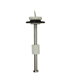
The manual applies jointly to the TGW (water) and TGT (fuel) series. For diesel and petrol tanks, read the manual for the TGT tank sender.
Application
The high-resolution dip-tube senders of the TGW (water) and TGT (fuel) series are suitable for monitoring the levels of all tanks on board. They are intended for vertical installation in water and fuel tanks and are screwed into the supplied flanges. This means they can be removed again at any time for inspection.
The measuring electronics are galvanically isolated from the housing. This is important to prevent galvanic corrosion. The TGW and TGT tank senders are therefore suitable for metal and plastic tanks.
Connection and wiring diagram

The diagram from the manual shows the philippi tank gauge from behind with terminals L, S, − and +. The sender is connected via its brown and white wires: the brown wire goes to terminal S of the gauge, the white wire to ground.
| Terminal / lead | Function according to the wiring diagram |
|---|---|
| L | Lighting + |
| S | Signal from the TGx tank sender |
| − | Ground |
| + | Power supply +12 V |
| Series resistor for 24 V on the lighting | 1 kΩ |
| Series resistor for 24 V on the power supply | 180 Ω |
For 24 V systems there is the RTURO series resistor set with one 180 Ω and one 1 kΩ resistor (see accessories).
Switching points by sender size
| Tank sender | Number of switching points |
|---|---|
| TGx 200 | 7 |
| TGx 250 | 10 |
| TGx 300 | 13 |
| TGx 350 | 16 |
| TGx 400 | 19 |
| TGx 450 | 23 |
| TGx 500 | 26 |
| TGx 600 | 32 |
| TGx 700 | 38 |
| TGx 800 | 44 |
In the manual, "x" stands for W (water) or T (fuel).
Installation: hole and dimensions
- The required hole diameter in the tank is at least 42 mm.
- The sender head including the flange protrudes 32 mm above the tank surface.
- Mounting position: vertical, ± 20°.
- The sender is screwed into the supplied flange.

More on choosing the right sender and on installation: Level measurement in the tank and the tank sender finder.
Accessories and matching instruments
| Item | Purpose | Order no. |
|---|---|---|
| Round gauge Water52 | Matching philippi gauge for water | 2 0778 0601 |
| Series resistor set RTURO | For 24 V, 1 × 180 Ω and 1 × 1 kΩ | 2 0800 2000 |
| Threaded adapter flange GWA | For SAE hole | 6 6010 9010 |
| Sealing cap TRV | Seals the tank during maintenance | 6 6011 9000 |
Accessories are not included in the scope of delivery.
Technical data
| Measuring resolution | approx. 16 mm |
| Sender range | 5–180 Ω |
| Connecting cable | 2 × 0.34 mm², length 20 cm |
| Mounting position | vertical, ± 20° |
| Temperature | −10 to +70 °C |
| Overpressure | max. 1 bar |
| Protection rating | IP65 |
| Hole in the tank | at least 42 mm |
| Sender head incl. flange | 32 mm above the tank surface |
Note from the manual: philippi cannot monitor compliance with the operating instructions, nor the conditions and methods of installation, operation, use and maintenance. philippi therefore accepts no liability for damage resulting from faulty installation or improper operation.
Disposal
When disposing of the product, observe the applicable local regulations and use the collection points for waste electrical and electronic equipment.
For questions about installation or for a repair: Contact · Warranty and repair · All manuals
Manual didn't help? We are happy to help.
Contact