

BLM2 Battery Monitor Manual: Installation, Shunt and Settings.
The BLM2 battery monitor shows the state of charge, charge and discharge current, voltage and remaining time of the main battery on a touchscreen, plus the voltage of up to two further batteries. The SHE 348 shunt in the battery’s negative path takes the measurements. Here you will find installation, wiring, settings, NMEA 2000 connection and operation.
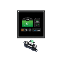
What the BLM2 does
- State of charge, charge and discharge current, voltage of the main battery
- Remaining time until the adjustable capacity alarm
- Voltage of up to two additional batteries
- Optional: current of a solar system via a second SHP 348 shunt and operating data of a philippi ACE charger
- Alarms when a capacity threshold is undershot and for undervoltage or overvoltage
- Integration into an NMEA 2000 network to show the battery status on the chartplotter
Scope of delivery and accessories
The BLM2 monitor comes with two pluggable terminals (3-pin), two ASH1 fuse holders with FSS 1 A fuse and the user manual. The BLM2 set includes the SHE 348 shunt.
| Accessory | Purpose |
|---|---|
| SHE 348 shunt | Capacity measurement of the main battery (included in the set) |
| SHP 348 shunt | Current measurement, e.g. of a solar system |
| TEMP-BT temperature sensor | Display of the battery temperature |
| ACE-LIN interface | Connection to a philippi charger of the ACE series |
| N2K cable | Connection to NMEA 2000 |
Intended use and safety
The BLM2 works only together with the SHE 348 shunt on extra-low DC voltage of 8–60 V. It is designed for use on yachts and may only be operated in enclosed spaces protected from rain, moisture, dust and condensation. Do not install where there is a risk of explosion from gas or dust, and not outdoors.
- No modifications may be made to the unit, otherwise the CE mark becomes void.
- Have the connection carried out only by qualified electricians and disconnect the battery cables first.
- Observe correct polarity. The supply cables to monitor and shunt must be fused.
- The unit is not intended for use by children.
Warranty: two years from the date of purchase. Excluded are defects caused by incorrect connection, ingress of liquids, oxidation due to condensation and lightning strike; consequential costs and natural wear are not covered. philippi accepts no liability for damage resulting from incorrect installation or improper operation.
Mounting the monitor
Mount the monitor in a protected, dry and clearly visible place. The mounting cut-out is 85 × 85 mm and the minimum depth 35 mm. On the back there is a 3-pin terminal for the power supply and the communication cable to the shunts, a 2-pin terminal with a potential-free relay contact and the slot for a micro SD card for software updates.
The monitor’s power supply may be interrupted at any time: the battery data is stored in the SHE 348 shunt. The shunt should therefore stay permanently connected to the battery. When the monitor is off, the shunt goes into sleep mode and draws only 2 mA. If the system remains uncharged for more than three months, disconnect the shunt from the battery as well.

Monitor and shunt are connected by a single-core LIN bus cable. Any cable can be used; for mechanical reasons with a cross-section of 1 to 1.5 mm².
Connecting the SHE 348 shunt
Mount the shunt in a protected, dry place as close as possible to the service battery, without contact with the positive terminal. The shunt sits in the negative path:
- Connect the side marked B− to the negative terminal of the main battery with a short, thick cable (35–70 mm²). With several batteries in parallel, to their common negative pole.
- Connect all negative cables of the on-board system and charging sources and the negative poles of up to two starter batteries to the side marked V−. Recommended: combine everything on a ground busbar and run a short cable from there to V−.
- Connect the sense wire (+1) to the positive terminal of the main battery via an inline fuse holder with 1 A. Through this wire the shunt measures the voltage and is powered at the same time.
Important: no other cable may be connected between B− and the battery negative pole. Otherwise not all currents are recorded and the battery management does not work.
| Shunt terminal (5-pin) | Function |
|---|---|
| 1 (+1) | Voltage measurement of the main battery and supply of the shunt. Disconnect only during winter storage so that the capacity is recorded without gaps. |
| 2 (+2) | Optional: voltage of a second battery bank, e.g. the starter battery |
| 3 (T−, T+) | Optional: TEMP-BT temperature sensor, attached to the outside of the battery housing. The temperature is for information only and affects neither capacity calculation nor charging. |
| 4 (LIN) | LIN bus to the monitor and to the ACE charger |
| Shunt LED | Meaning |
|---|---|
| rapid flashing | Firmware update in progress |
| flash every second | Normal operation |
| flash every 5 seconds | Sleep mode, monitor is off |
SHP 348 shunt for solar or load current
The optional SHP 348 shunt measures, for example, the solar current. Mount it protected and dry near the battery in the negative path of the solar system; its negative pole goes to the side marked V−. Terminal 1 (+1) measures the voltage and powers the shunt, terminal 4 (LIN) connects it to the monitor, ideally with 1 mm².
ACE charger via the ACE-LIN interface
For the BLM2 to communicate with a philippi ACE series charger, the ACE-LIN interface is fitted in the charger. On the ACE 12/60 and ACE 24/30 models it replaces the integrated monitor.
- Disconnect the charger from the AC mains.
- Remove the front cover, break out the metal tab for the cable entry with flat-nose pliers and fit the rubber cable grommet.
- Set the charger’s DIP switches A, B, C, D to “1111”. Only then can the charging curve be set on the monitor, including a user-defined one. Otherwise the curve selected via the DIP switches applies.
- Plug the 16-pin connector of the ribbon cable into the red connector on the main board. The interface board is held by three plastic clips in the housing.
- Connect the LIN terminal of the interface with a single-core cable (ideally 1 mm²) to LIN on the shunt and on the monitor. The order on the line does not matter; as LIN is provided twice on the interface, monitor → charger → shunt is a good choice.
Important: monitor, shunt and charger must have the same negative potential, i.e. be connected to a common negative point (battery negative).
Settings
Open the settings on the main screen via the gear symbol at the bottom centre. The PIN is 1234 as delivered. The areas are Display, Battery, Charger, Energy source and Alarms.
Display
Language, maximum brightness (20–100 %), automatic brightness, night mode threshold, auto standby, change PIN, Raymarine mode (NMEA 2000 only), factory settings, save or load the configuration on the SD card, and software and hardware version.
Calibrating the night mode threshold: cover the light sensor at the centre left of the display with your finger, read the value in brackets, add 2 and enter it. If the measured value falls below it, the display is dimmed; if it rises above the threshold plus 10, it is lit normally again.
Battery
Set during commissioning. The battery should be fully charged; if it is not, charge it fully afterwards so that the display synchronises.
| Setting | Note |
|---|---|
| Name | shown in the battery symbol |
| Nominal capacity | 1–9999 Ah. Only set with a full battery: the display is set to 100 % and all counters to 0. |
| Nominal voltage | 12, 24, 36 or 48 V |
| Battery type | GEL, FLOODED, AGM, Lithium or INDIV; determines the detection of “full” and “empty” |
| Ah efficiency (CEF) | 95 % from the factory, adjusted automatically over the last four cycles. Lead batteries are at 80–95 %; below 70 % the battery has reached the end of its life. |
| Cycle depth | discharge from which a cycle counts: starter batteries 10–20 %, GEL up to 50 % |
| Peukert exponent | typically 1.27 for lead, 1.02 for lithium; corrects the remaining time at high currents |
| Name battery 2 / 3 | Name of the additional batteries |
| Shunt info | Type and software version of the shunt, firmware update from the SD card |
Shunt firmware update: provide the file on the SD card, pull off the green plug on the shunt, press START and plug it back in within 30 seconds. The progress is shown on the screen.
Charger
With an ACE charger connected: charging curve, Charge Control (control by charger or monitor), device type and software version. With the custom curve, boost voltage, maximum boost duration, float voltage and the current threshold for switching to float charging can be set. Without a connected, mains-powered ACE charger, no settings are possible.
Energy source
Name of the source on the SHP shunt, reset of the capacity counter, and software version and firmware update of the SHP (as with the SHE).
Alarms
A battery alarm always appears in the battery symbol. In addition it can be output visually (display backlight flashes), audibly (internal buzzer) and via the potential-free relay (max. 1 A). Touching the screen acknowledges the alarm; it can also switch off by itself after an adjustable time (0–255 s, 0 = always on). A short press on a line switches the audible alarm on or off, a long press (over 2 s) opens the threshold.
| Battery | Alarm | Range |
|---|---|---|
| Battery 1 | Capacity alarm | 10–80 %, default 50 % |
| Battery 1 | Battery empty / deep discharge | 20 % / 0 %, set by the battery management |
| Battery 1 | Overvoltage | 14–32 V |
| Battery 1 | Overtemperature | 40–60 °C |
| Batteries 2 and 3 | Undervoltage / overvoltage | 9–24 V / 14–32 V |
An additional battery is detected as soon as more than 1 V is present at +2. Voltage alarms trigger when the threshold is undershot or exceeded for 30 seconds. For 24 V batteries the voltage alarms must be adjusted.
NMEA 2000
For the connection, plug the N2K cable into the 4-pin connector and connect it to the network via a T-piece (Micro-C, M12). The monitor needs its own power supply and is not powered via the network. The data is sent every 2.5 seconds, including PGN 127506 (DC Detailed Status).
Each battery needs a unique instance. Usually instance 0 is selected; if the data does not appear on the plotter or on the wrong page, choose a different one. Two philippi devices on the network need different device instances. You set the monitor’s instance under Display, and that of batteries 1 and 2 under Battery. On Raymarine plotters the instances must start with 0.
Operation and displays
The buttons at the bottom switch between the battery, energy and charger screens and the setup. The charger screen is only active with a connected, mains-powered ACE charger.
On the left, the battery screen shows the main battery. The arrow shows current and voltage: green means charging, red discharging. The bar height shows the fill level; the grey part at the bottom is the unusable capacity from the last complete discharge and an indication of the battery’s condition. A short press on the symbol switches between capacity in %, in Ah, remaining time and temperature. Up to two additional batteries appear on the right.
| Message | Meaning and remedy |
|---|---|
| Not synchronized | The shunt has been restarted. Fully charge the battery with a charger; the message then disappears. |
| Recharge battery | Capacity threshold undershot, charge at the next opportunity |
| Battery empty | below 20 % remaining capacity, charge immediately |
| Battery deeply discharged | switch off all loads and charge immediately |
| Temperature | Battery temperature outside the permissible range |
The charger screen shows charging current and voltage, the charging phase (bulk, absorption, float), the battery temperature and the mains voltage and frequency. LIMIT +/− lowers the charging current in 10 % steps down to 40 %, for example with a weakly fused shore connection. Night mode switches off the fan on units that have one and limits the charging current; it ends automatically after 8 hours.
Battery history
A long press (2 s) on the battery symbol shows charging cycles, deep discharges, average depth of discharge over the last 10 cycles, unusable capacity, battery usage and maximum currents, voltages and temperatures. After replacing the battery, reset the counters with the upper “000” button and PIN, and the min/max values with the lower one.
How the BLM2 calculates capacity
- Full charge: a lead-acid battery is considered full when for 3 minutes either 13.4 V is held, the charging current is below 2 % of the capacity and more has been charged than drawn, or 14.0 V at less than 1 % charging current. Adjusted values apply to other battery types.
- Unusable capacity: if the voltage falls below certain thresholds prematurely, the BLM2 sets the state of charge to 20 % or 0 % and shows the missing capacity in grey. This only works if the battery is discharged to the first discharge limit (roughly below 11.5 V). philippi recommends doing this once a year at the start of the season.
- Remaining time: time until the capacity alarm at the current consumption, Peukert-corrected, maximum 99.9 hours. When charging, the BLM2 shows the time to about 95 %.
- State of charge: when charging, the current is weighted with the Ah efficiency (CEF).
Tips and software update
- If “Not synchronized” does not disappear despite a full charge, change the nominal capacity by 1 Ah.
- If full-charge detection does not work, check the charging voltage and set the battery type to FLOODED as a test.
- Check each charging source individually: with the loads switched off, the charging current must be positive. Only B− of the shunt may be connected to the battery negative pole.
Monitor software update: copy the file without folders onto an empty micro SD card (FAT32), insert the card at the back, disconnect the power supply and switch it on again. The update starts automatically. If the monitor starts normally, no card was detected or the software is up to date.
Technical data
| Supply voltage | DC 8–60 V |
|---|---|
| Monitor current consumption | 60 mA at maximum brightness, 5 mA in sleep mode |
| Shunt current consumption | 20 mA, 2 mA in sleep mode |
| Shunt resistance | 0.1 mΩ |
| Measuring range U1 | 0–60 V, resolution 30 mV, accuracy 0.25 % |
| Measuring range U2 | 0–35 V, resolution 30 mV, accuracy 0.25 % |
| Current measuring range | −600 to +600 A, accuracy 0.5 % |
| Shunt current rating | 300 A, 600 A for 1 min, 1500 A for 0.5 s |
| Relay contact | max. 1 A |
| Temperature measurement | −15 to 60 °C, accuracy 1 K (external sensor) |
| Monitor dimensions | L 105 × W 105 × D 40 mm |
| Shunt dimensions | L 118 × W 40 × H 65 mm, M8 studs |
Conformity: EU Directive 2014/30/EU “Electromagnetic Compatibility”, immunity EN 61000-6-1, emissions EN 61000-6-3. For disposal, observe local regulations and use the collection points for waste electrical equipment.
Manual didn't help? We are happy to help.
Contact