

Manual LAE 236: Shore power unit with 6 circuit breakers.
The LAE 236 shore power unit protects the onboard 230 V system and switches up to six load circuits via 2-pole thermal circuit breakers of 10 A each. This page summarises the installation notes and technical data from the manual.
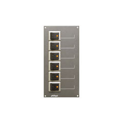
Use and design
The LAE 236 protects the onboard 230 V system. Six 2-pole thermal circuit breakers of 10 A protect and switch up to six load circuits. The electrical connection is made via 6.3 mm flat-plug terminals on the back of the panel. The manual contains no wiring diagram.

Important installation notes
- Work on low-voltage AC 230 V/50 Hz system components may only be carried out by qualified electricians.
- The LAE 236 may only be installed with an upstream RCBo (RCD/MCB) of maximum 25 A at the input.
- The back must be protected against accidental contact: with a non-combustible cover, or so that access is only possible with a tool.
- Leave sufficient clearance to the rear wall or cover because of the possible fire hazard.
- The installation location must be dry and protected.
- The European standard EN ISO 13297 must be observed during installation.
Technical data
| Operating voltage | AC 230 V / 50 Hz |
| Circuit breakers | 6 × 2-pole, thermal, 10 A each |
| Connections | 6.3 mm flat-plug terminals |
| Upstream protection | RCBo (RCD/MCB) max. 25 A at the input (external) |
| Dimensions | W 105 × H 210 × D 70 mm |
More on this topic: Shore power on board · Onboard electrical planning. For questions about installation or for a repair: Contact · Warranty and repair · All manuals
Manual didn't help? We are happy to help.
Contact