

Manual LAE 235: Shore power unit with RCBo and socket.
The LAE 235 shore power unit protects the onboard 230 V system with a 16 A, 30 mA RCBo, shows the shore supply connection with an indicator light and provides an earthed socket. This page summarises the connection, wiring diagram and technical data from the manual.
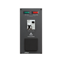
Use and design
The LAE 235 protects the onboard 230 V system with a 16 A, 30 mA RCBo (residual-current circuit breaker with overcurrent protection). An AC indicator light shows the connection to the shore supply. Loads can be plugged straight into the earthed socket. The electrical connection is made via a terminal strip on the back of the panel.

Important installation notes
- Work on low-voltage AC 230 V/50 Hz system components may only be carried out by qualified electricians.
- The back must be protected against accidental contact: with a non-combustible cover, or so that access is only possible with a tool.
- Leave sufficient clearance to the rear wall or cover because of the possible fire hazard.
- The installation location must be dry and protected.
- The European standard EN ISO 13297 must be observed during installation.
- Use the supplied ferrules for the connections.
Wiring diagram and terminals

| Terminal | Function |
|---|---|
| 1 | Shore connection: grey phase L, blue neutral N, green/yellow protective earth PE, up to max. 3.6 kW (16 A) |
| 2 | Onboard system output: grey L, blue N, green/yellow PE, up to max. 3.6 kW (16 A) |
The wiring diagram shows a 2-pole MCB of max. 16 A on the shore side. All cables are 2.5 mm².
Technical data
| Operating voltage | AC 230 V / 50 Hz |
| Protection | RCBo (RCD/MCB) 16 A, 30 mA |
| Shore connection / onboard system | each up to max. 3.6 kW (16 A) |
| Connecting cables | 2.5 mm² |
| Dimensions | W 105 × H 210 × D 100 mm |
More on this topic: Shore power on board · Onboard electrical planning. For questions about installation or for a repair: Contact · Warranty and repair · All manuals
Manual didn't help? We are happy to help.
Contact