

Manual LAE 234 LG: Connecting and Installing the Shore Power Unit.
The LAE 234 LG shore power unit switches between shore power and generator, monitors the 230 V system on board and protects the load outputs with an RCBo (residual-current circuit breaker with overcurrent protection). Four double-pole thermal circuit breakers (10 A) switch the individual load circuits, and an AC voltmeter shows the on-board voltage. This page summarises the connection, wiring diagram and technical data from the installation manual.
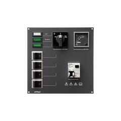
The manual applies to both the LAE 234 LG and the LAE 234 LGW. For the version with inverter changeover, read the manual for the LAE 234 LGW.
Use and design
The LAE 234 LG and LAE 234 LGW shore power units are used to switch between different AC sources such as shore power, generator and inverter, to monitor the 230 V AC system on board and to protect the load outputs with an RCBo (residual-current circuit breaker with overcurrent protection). The LAE 234 LG model contains a changeover switch for shore power and generator, the LAE 234 LGW model a changeover switch for shore power, generator and inverter.
The green mains indicator lights for shore power, generator or inverter show the applied mains voltage (operational readiness). The AC voltmeter shows the on-board voltage. The four double-pole thermal circuit breakers (10 A) are used to switch the individual load circuits. The electrical connection is made via a terminal strip on the rear of the panel.

Important installation notes
- Work on low-voltage AC 230 V/50 Hz system components may only be carried out by qualified electricians.
- Installation must ensure that the rear is protected against accidental contact: either with a non-combustible cover or so that access is only possible with a tool.
- Make sure there is sufficient clearance to the rear panel or cover because of possible fire risk.
- The installation location must be dry and protected.
- The European standard EN ISO 13297 must be observed during installation.
The installation instructions are part of the component delivery. Keep them in a safe place for later maintenance work and pass them on to subsequent owners.
Wiring diagram and terminals

The diagram from the manual shows both versions: the LGW version on the left, the LG version on the right. On-board outputs 1 to 4 are only drawn on the left-hand side. All cables are specified as 2.5 mm². In the diagram, an MCB-2P of max. 16 A is drawn upstream of each input.
| Terminal | Function (LG version) |
|---|---|
| 1 (L, N, PE) | Shore power input, up to max. 3.6 kW (16 A) |
| 2 (L, N, PE) | AC generator input, up to max. 3.6 kW (16 A) |
| 4 to 7 (L, N, PE) | On-board outputs 1 to 4, each via 10 A thermal circuit breaker |
| 8 (L, N, PE), from 2015 | On-board output with RCBo (RCD/MCB) 16 A, 30 mA |
Terminal 3 (inverter input) exists only on the LGW version.
Technical data
| Operating voltage | AC 230 V / 50 Hz |
| Input terminal 1 | Shore power up to max. 3.6 kW (16 A) |
| Input terminal 2 | AC generators up to max. 3.6 kW (16 A) |
| Input terminal 3 (LGW only) | Inverter up to max. 3.6 kW (16 A) |
| Main protection | RCBo (RCD/MCB) 16 A, 30 mA |
| Output 1 to 4 (terminals 4 to 7) | Thermal circuit breakers 10 A |
| Output terminal 8 (from 2015) | RCBo (RCD/MCB) 16 A, 30 mA |
| Dimensions | W 210 × H 210 × D 110 mm |
Conformity and disposal
According to the manual, the product meets EU Directives 2004/108/EC (electromagnetic compatibility; immunity EN 61000-6-1, emissions EN 61000-6-3) and 2006/95/EC (electrical equipment for use within certain voltage limits). Conformity is confirmed by the CE marking. Observe the applicable local regulations for disposal and use the collection points for waste electrical and electronic equipment.
More on the topic: Shore power on board · Generating energy on board · On-board electrical system planning · Circuit breaker LAE 205. For questions about installation or for a repair: Contact · Warranty and repair · All manuals
Manual didn't help? We are happy to help.
Contact